Showing posts with label bridge. Show all posts

Monday, February 14, 2011

Post Progress Report from P1

In continuation to the last project (in an effort to prepare it for submission to the competition) I made the following rendering. I thought I'd post it here to give a better impression of the bridge's scale then that which was given at the presentations.

Comments for improvements welcome.

Monday, February 7, 2011

Saturday, February 5, 2011

Progress Report 7

Just a quick update...
The components of the bridge are now almost complete. Below are images of the bridge before the support cables and twisting have occured. Now on to that stage...
Note the bridge's repetative elements. The bridge could be made shorter or longer by adding or subtracting components respectively.


Image 1

Image 2

Friday, February 4, 2011

Progress Report 6

Working out the final details of the connections for the railings and the over-all cross bracing and stabilizing system for the suspended bridge which will now appear lighter and actually hang from the large concentric rings instead of sitting on them. This will better lend to the impression, now correct, that the entire bridge is suspended via the tension in the cables and the connections rather then just creating the impression/illusion that is the case.


Image 1

Image 2

Image 3

Thursday, February 3, 2011

So, I broke my back today and at the same time trying to fine-tune my design, but as soon as I talked to Vince, I realized my back was the least of my concerns. The good news is that he said my design was better developed then the last time he saw it and the bad news is I have to “keep developing” (story of my life). Damn my back! Anyways, here are my initial sketches. And as T says, Keep Calm and Carry On!


Wednesday, February 2, 2011

A MITCH (ha) needed update

Last time, on Mitch, we saw various plants which I intended on 'biomimicking,' including Mangroves, Banyan trees, Whitebark Pine, and my personal favourite, creeper tendrils.

As I explored my options more, I increasingly seemed to be turning to the creeper tendrils, which seem like a great opportunity to emulate for my bridge. The twisting of the tendrils allow for a much greater rigidity than the minimal form of them would suggest.
As I moved forward with this design, it began to develop as a bridge which literally twisted in the same manner as the tendril, but as a bunch of them.

The central sketch in this image shows the thinking behind this. It would be a series of rings, with steel rod supports between to provide the overall structure. These supports would be connected with details like the ones shown below.

I had even begun to develop a script that would allow the bridge to adapt to different conditions, which may be an unnecessary use of grasshopper.

Upon further though, I felt that the number of tendrils was beginning to take away from the concept, and it was beginning to look unlike a creeper at all. I took a step back and began to think about how the plant actually supported itself, leading me to two solutions, twisting, and the cross section of the tendril itself.
This, however, was abandoned. Going back to twisting, I began to look at tensegrity structures as suggested in a critique.
Like this, but on its side. I like that tensegrity structures allow for a great deal of strength with relatively little structure, much in the manner of the creeper tendril. So, this idea is being developed, as can be previewed in the following details.

Monday, January 31, 2011

Progress Report 5

Image 1 - The large rings that form the spine of the bridge and the anchor rings that will guide the path of the steel cables.

Image 2 - Since the steel cables are twisting, both the large rings and anchor rings will require a high level of flexibility as to their rotation. Once the final rotation is set, the components can be bolted and welded in place with minimal welding.

Image 3 - One of the anchor ring components in an exploded detail.


Image 1

Image 2

Image 3

Sunday, January 30, 2011

Progress Report 4

The spine of the bridge will consist of a series of ridged walkways that serve as the path across the bridge and as anchor supports. Below are two exploded renderings of these platforms, exploring their assembly and a possible presentation style for the final submission.


Image 1


Image2

Saturday, January 29, 2011

General Detailing - Bridge Continued

Bridge - Range of Motion and Ballast Placement. I was trying to determine the optimal range which would allow for the ballast to have the most effect.

Pin Connection. This is for the main arms of the bridges (there are four). The connection would allow them to rotate. Now that I think about it I may need to design a stop so the bridge doesnt fold up completely.

Cast Steel Shear Connection/Walkway. This connection allows for the walkway to fold up flush with itself which would not have been possible if the metal grate was placed on top of the connections.

Ballast Wheels - This is the device which would attach the ballasts to the arms and allow them to move as the water level rises and falls.

Ballast Structure. Preliminary attempts at designing the structure for the ballast and trying to reduce the overall weight by leaving only the load bearing portions of the members. I also was figuring out how the ballasts would be clad and where the seams would be.

Thursday, January 27, 2011

My newest contestant is a “water strider”, also known as the “Jesus-bug”; fitting, since it’s a bug that floats on water. This insect relies on surface tension in order to walk on top of water. The legs on these insects are designed to keep afloat as well as guide themselves across rivers, ponds, and streams, using its middle legs to guide and its forelegs as rudders. Fun fact: Their legs are water resistant.
As for the design I’m still designing a bridge, but now, the bridge will be floating above water, much like the lily pad, but this design will focus mostly on the mechanics of how it will work. As of now, I’m trying to design hinges, that will allow for movement, depending on the water levels, tension from the link between each platform, pontoons to help keep it float above water, but most importantly the hinges (legs), which will be the core of all its mechanics as they will be adjustable and acts as the links.

Tuesday, January 25, 2011

Progress Report 3

Starting to work out some of the details for the central spine of the design.
The detail seen in image 1 is more rigid and as such, is less likely to twist due to moment. The detail in image 2 however is likely to be closer to the final design. This is due to the fact that the twisting of the steel cables will produce angles that will have to be dealt with by moving the anchor* rings in multiple directions.

* - I name these "anchor" rings since they anchor the spine to the steel cables. The resultant bridge is self supporting by virtue of the bunching and twisting of the cables, just as muscle tissue and plant cells are.


Image 1

Image 2

Monday, January 24, 2011

Progress Report 2


First thing's first, hey Jess, ouch, looks serious, hope you get well soon!

As for progress, below is an initial modeling exploration in Rhino. Needs a lot of work but the general idea is starting to take form...

Pick and Choose

As I sit in studio questioning which design options I’m going to decide on, I thought maybe I should share my thoughts with you in order to narrow it down. I’m pretty settled on designing a bridge, as it’s something that I’ve always wanted to do, but I don’t know in which application I should design it (highway, pedestrian, heavy locomotive, etc.).

My initial design was inspired by rock formation, which would mimic the patterns to create a system of bridges. I would most probably design this for a highway system, but am not sure on how far I would be able to take it. Though my sketches seem to broadcast an elegant design.

The second option was to design an ice bridge for ice-truckers in Fort McMurray Alberta or any of the Territories that work with large machinery for work, such as oil sands, mining, etc. The bridge is to be built either of triangulation patterns formed by natural ice crystals/ icebergs, or as a honeycomb structure, since the honeycomb is able to span long distances. The only thing that worries me is that it’s too generic.


The third option was to design a pedestrian bridge close to water, possibly near the East Coast, as a “reflection” walkway. This bridge would be designed to work with both high tide and low tide. I took the inspiration from the lily pad, for obvious reasons as it floats above water. The lily pad is made up of hundreds of veins on the underside, in varying thicknesses, which hold within it air pockets. If any of you remember grade 10 physics, you would know that the reason why something floats is because the pressure of the air within a form/ unit displaces the same or less amount of water underneath it, thus keeping it in equilibrium (floating). However, the only problem I have with creating a bridge that levitates on water (with structure underneath of course) is the problems of rust. I’m not sure if something like this is feasible.


In the Beginning.


In my initial research, I found myself drawn to the spectacular rooting mechanisms of Mangroves, which I had the opportunity of viewing firsthand on a visit to the coastal mangrove forests in the Dominican Republic.

Mangroves are able to root into shallow coastal marshes, where few other species of plant are able to survive, providing habitats for a variety of different fauna. A young mangrove can even be 'deployed' floating until it finds a suitable area to root.
Looking at these roots led me to the Banyan tree, which grows from the top of the forest canopy down towards the ground, creating light, near space frame structures.


However, due to the obvious structural difficulties of building a structure from the top down, along with the randomness of the space frame created, this idea was cut down. (Nice Pun!)

Next up then, are various creepers.


(See it happen at 1:40) A creeper tendril will wind itself until it touches a potential support, wind itself around it, and then strengthen itself by creating a curling 'bridge.'

This interesting spiraling has led me to seek out other forms of torsion strengthening in nature, leading me to the Whitebark Pine, where the direction of the wood fibers can deviate up to 30 degrees from the direction of growth.

More on that here: http://asknature.org/strategy/e70b6b7753773a7177fe8358ec26ed2c

Hopefully this will lead to some interesting structures. We will soon find out.

Friday, January 21, 2011

Follow-ups to some reviews...

As many of the ideas presented this past week were still developing, it became evident that some quick precedents may be useful in fueling a greater sense of what can actually be accomplished both from a technical and biomimetic level.

Heatherswick's Rolling Bridge

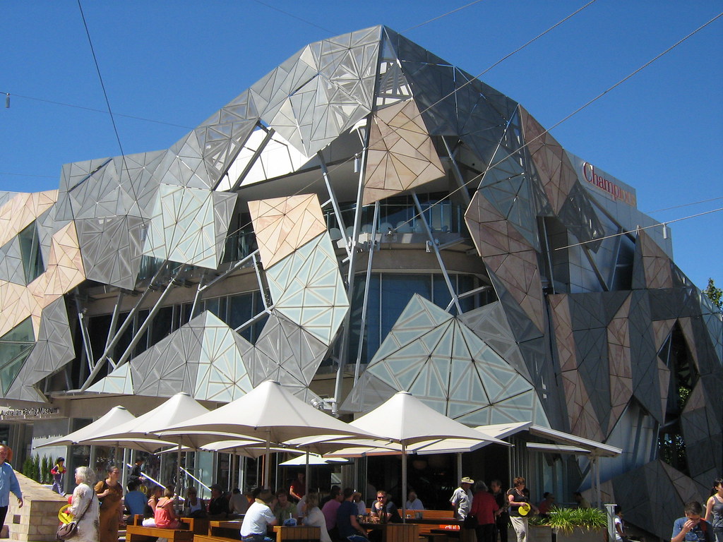
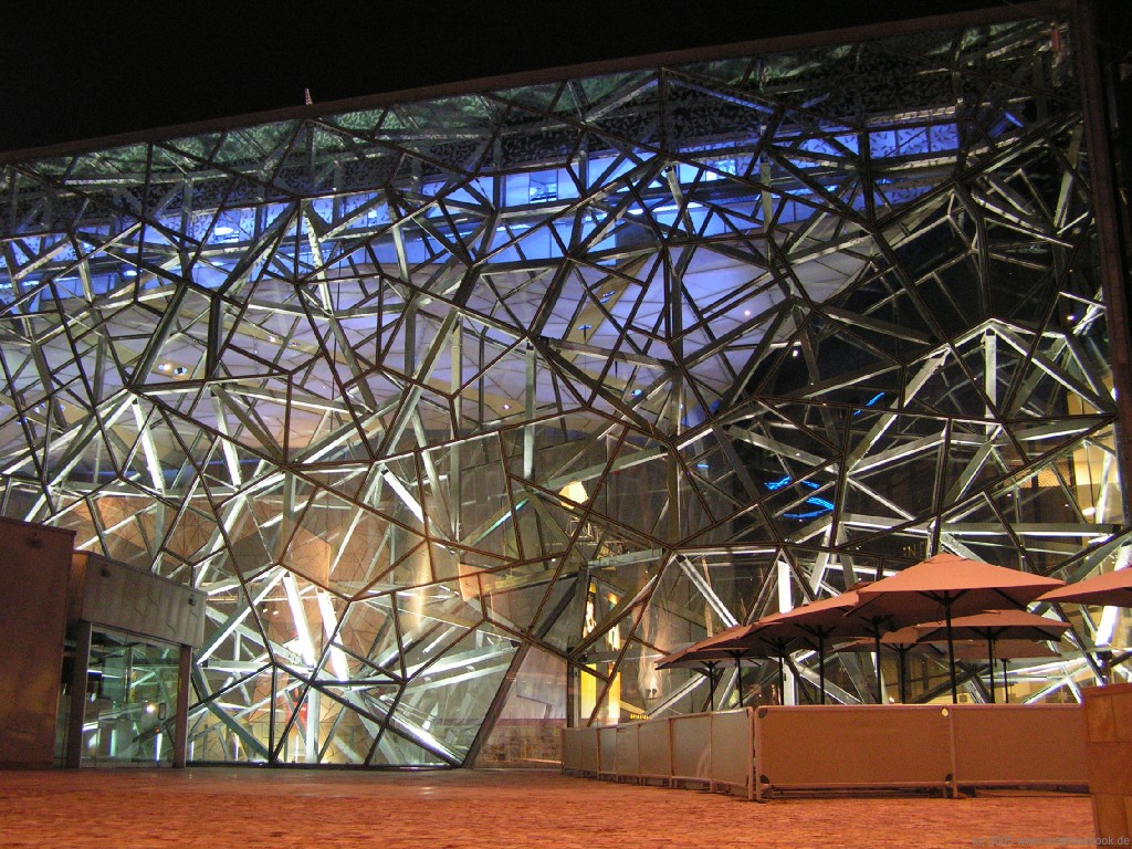
Federation Square in Melbourne, Australia (LAB Architecture Studio)

Component-basis of Design with Kinematics


Theo Jansen's Kinetic Sculptures/Creatures