Showing posts with label Perry. Show all posts

Sunday, April 10, 2011

Disaster Report 4B

SO.... After 3 days of toiling, I still have not much of a clue as to how to work the overall canopy... and with that the look of the building.... crap.

On the flip side, at leats some of the structure got somewhat done.... I think... the dark grey portions represent the concrete base, and the upper half are steel 'trees' that reach up into the roof... argh...

While the center of the space seems fine, the ends are where the REAL problems start... how do they end you ask? I'll let you know when I figure it out... but here's the summary. the long corridor you see in the first render and this one on the left start and end at the main entrance and the small theatre respectively with the pool and large training facility on its flanks. so that basically covers MOST of the BIG programming... leaving the cafeteria and the design studio that have been planned for on the upper floors... location still to be finallised... (they keep moving around)...

Saturday, April 2, 2011

P4A Submission

As mentioned before in previous post, I was exploring a passive controlled biomimetic system that would allow for shading and venting without the need for any electrically powered components through out its operation. Seen here on the left, is the fin system at its maximum spread providing shade for the roof.

System as seen from the interior of the building. Here the heat sensitive pistons can be seen.


System in its opened (top) and closed(bottom) positions.


Heat Activated Piston Control that works on the principle of air expansion under heat. Being located close to the roof where the temperature in the space would be at its highest, these pistons push the fin assembly upward and allows for the provision of shade as well as opening vents to allow for excess hot air to escape.

Wednesday, March 23, 2011

Project 4A progress report

Just a quick update on the envelope progress. A couple of things still need to be worked out such as the actually fin shape. Judging from the current outcome, they may have to trimmed down slightly in order to avoid knocking into the adjacent units. Though the position in this first render of the units is wrong, I don't think it will be a problem in the overall scheme.
Note: All cells will have glazing like the two in the middle.


Detail of Fin pivot connection in the open position.

Detail of the fin pivot connection in the closed position.


A look at the piston assembly. (closed position)


View from inside the space looking up at the roof assembly. Piston in open position in the foreground, and closed position in the background.


Detail of 3-point connection.


Sunday, March 20, 2011

The Envelope System

As part of project 4A, I envisioned a type of envelope that would be able to react according to the amount of sunlight that would pour into the space. Given the form of the roof and the changing angle of the sun during the day, I needed a unique shading system that could provide light into the space, yet be able to defuse it when direct light hit. Rather the make the system react to the intensity of light, I designed it to be reactive to temperature. Taking into account physical princples of hot air rising, and seeing that the roof would liekly be the hottest area of the building, the system created is built to vent and shade the roof to control the overall temperature of the space.

Borrowing of one of the ideas for a biomimetic system I envisioned back in Project 1, where by an air bladder with air in it would react to high temperature by expanding and becoming more bouyant (thereby opening the louver fins). There where several problems here, first of which the overall weight of the fins and that the air would not expand enough to lift the steel fins, and second, the amount of air required.

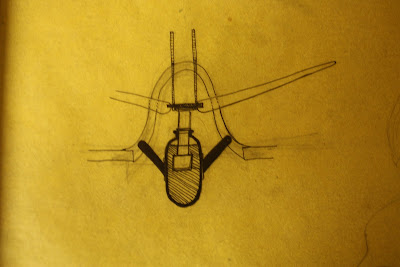
With these problems in mind, the system was redesigned into a form of a much lighter unit that comprised of several smaller fins that would open when it rises up much like a blooming flower. This option allowed for a greater difference in the amount ofshade provided depending on how much sunlight was at any given location on the roof.


In theory, this would work, but it is doubtful that enough heat could be generated in order to make the units float, so suggestions were made to use barometric pressure in order to achieve greater potency. Barometric pressure on the other hand requires significant changes in atmospheric moistur content, and in the desert...On a side note, the structural framing of the roof was also designed to accomidate the individual units seeing that not every part would need shading as upon opening, a single unit would be able to cover its surrounding cells... but a hexagonal grid would be established. (its also structurally sound)
Fin types was also thought of with different ones with varying degrees of shading. But the main problem had still to be sholved. So I built a model to test its effectivness in the real world. As can be seen below, the kinetics of the spikes work perfectly so long as there is a force to push them up and gravity pretty much takes care of the rest, but of course, the deployment was still in question...


Some research later, I came up with a system that might work. Using a combination of air and water (though possibly some other type of liquid more sensitive to temperature.. mercury? poison...) it may be possible to create a valve that increases the air pressure by immersing it in the liquid when it heats up thereby providing sufficient force to raise the fin arms, and when the pressure is released, allowing a vacume to such the piston back into place. As a secondary, the gaps where the spikes emerge from the units housing (that bell shaped structure) could also act as vents to release hot air in the roof providing natural ventilation in the process. Note the hexagonal bottom plate that will attached to the aforementioned roof structure.


While it can be said to work, the question comes to mind whether or not it is possible to actually build one for the project submission seeing that it requires equipment that we simple don;t have access to.... Vince?


Creating Space


So it's been a while since I posted a blog, and have FINALLY decided to put up some of the stuff I've been developing for P4... To start this project, I first toggled around with the program, and figured that the most important aspect of the Cirque training facility is ultimately the training facilities and the need to keep them as functional as possible (no gimmicks in the way).

I first laid out some design principles

1. Combine Programs
2. Transparency where possible
3. All under one roof
4. Stay above grade where possible

The idea of a central common space with movable seating areas usable in both directions allows for the viewing of either the large training facility or the pool made for more areas to view makeshift performances in either facility. This also follows the first principle of 'combining programs'. (As seen in that tiny section on the right of the picture below).


Also seen here is a perspective of a section of the pool area with 'tree' columns to reach up to the roof. Instead of placing the outdoor auditorium in a seperate area outside the building skin, I decided to place it ON the large training facility creating a roof performance space with possible an opening roof system (think skydome). I also wanted to place the cafeteria on the upper levels as a nice end point in order to create a place that would allow for interection between staff, crew and visitors that would also be a great viewing point to see the entire facility (again think of the wolfgang puck restaurant at the springs preserve).


After setting the general space allocations, I then proceded to create the skin based on site and program perimeters. The space is meant to be one space with connections to multiple program in order to create continuity and also build visual dialogue between the various functional spaces. Though not all you see below will actually be solid cladding, this is the form for the moment until the rest ofthe sub-programming like the entrance and loading docks and parking are properly intergrated.


Friday, February 11, 2011

Project 2A (Cold Climate)

Located in Victoria BC, the Dockside Green Development Project is a LEED Platinum project that occupys 15 acres of former industrial waterfront. It is for the most part a brownfield development project that incorporates almost all aspects of sustainable design, from thermal, lighting, moisture and community.


The development has its own built in sewege treatment plant that filters and cleans most of the water that is used on site. As part of the idea of education, the Architects (Busby, Perkins + Will) made visiable the process by exposing the moving water instead of concealling it in underground pipes, making for an aesthetically pleasing environment.

The idea seems to borrow off marshlands from what I understand so far, and more research will be done to make certain this assumption. But what IS clear is that the achitects and developers have made a conscious decision to copy a natural system in the conception of the filtration system.


This then brings me back to the initial idea I had before about using the Kortright Centre here in Toronto (or rather Woodbridge) and their use of the 'Living Machine' in order to turn otherwise black water back into drinkable white water. While not the biomimicry of a single organisim, this comes from an entire ecological process found in the marshlands.


Sunday, February 6, 2011

Some Last images before the Final


So this is more or less it, (143MB of rhino file). This is pretty much the entire module without the decking and stair threads. There's a person in there to give it some scale. All in all a little larger then I thought it would be, and it seems when looking at the render that some of the members may or may not be adequate to support some of the kinetics involved. (might not have time to change things at this point) Oh well.... :[ my bed is calling me...

Saturday, February 5, 2011

Production Progress Report

Exploded view of the main Pivot assembly.


Just updating my progress. Model detailing is 75% finished, with the platform and truss beneth that still yet to be modeled. Render 1 is an isolated view of the pivot connection of the Boom Crane assembly.


Main pivot assembly showing the ball bearings inside.


Assembled pivot assembly with column units in place. (column texture is not final) Still haven't settled on a final one yet, though the shape is staying.


A look at the Boom Crane assembly with the attached ballast tank on end. 2 assemblies come together to form a complete module unit.


A quick render of the stair rotation pivot.


Monday, January 31, 2011

Design Development Final Thoughts


The development at this point to create a platform that has multiple uses depending on the configuration has uncovered several interesting possiblities. Depending on the tide levels, the stairs can either be a cascading steps that flow into the water, or a amphitheatre with a stage on the non-moving platform. Modelling will begin to see how this will work in layers in 3D with a furthur progress report ready by tuesday.


These 2 were an earlier permutation on how the system would work mechanically and in no way is evident of how the final form will look like.
Both are meant to be passive kinetic structures

Tuesday, January 25, 2011

Idea Development Part 2


This is the second idea in the works at the moment that plays with the expansion and contraction through passive means.
Using the Hoberman Sphere, this viewing platform expands and shrinks with the rise and fall of the tides. An air tight appendage is extended into the water and set at a given boyancy that places it at a set depth controls the size of the sphere.
The appendage works on the same principle as a submarine through ballast tanks and can likewise be found in several creatures in nature such as the Portugese Man O War.
More exploration into this is being made...

Idea Development Part 1


Fig. 1


Fig 2 Fig 3


Fig 4


Fig 5

Based on the structural venation of a leaf, this permutation is an exploration of creating a structure (Fig 1) that could double as both a canopy(as seen in the model) and/or a cantilevered platform. A closer look at the surface of the structure would deal with ventilation ducts that acted in a similar fashion to plant stomata by way of opening hinged vents (Fig 4), or circular apartures such as those drawn above (Fig 2).
An idea that came about in crit today suggested that the opening of the vent sizes would vary depending on the weight of the amount of people that occupied the space beneth the canopy. Exploration in this direction continues...