Showing posts with label Steel Connections. Show all posts

Saturday, April 9, 2011

Thoughts on structure...

In the interim submission for this project I focused on the exterior envelope, that protective and aesthetic facade the mediates heats gain and daylight and serves as the monumental and iconic presentation of the building to the surrounding context. The building itself was left simply as massing at this stage (Image 1).
I also delved into the assembly of this exterior skeleton's structure, proposing that it be assembled of 2 layers of steel structure, a heavier but simpler sub-structure overlaid with a lightweight super-structure. This allows the exterior facade to be independent of the building, minimizing the need for intermediary structure and minimizing the transfer of heat directly through conduction (Image 2)

I am now delving into the lightweight steel structure that will comprise the frame of the facility buildings itself. Steel allows for the flexibility of design and large spans that accommodate the program. It requires relatively simple foundations (which minimizes impact on the ground and requires less digging in the caliche).
With companies such as Schuff Steel Company Southwest based in Las Vegas and the large amount of steel discarded form casino projects, it is highly feasible that local steel could be found and reused in the project, allowing for savings and even LEED points for local extraction and recycled content.

The framing system is based on 2 radial systems of columns with a maximal depth of 20m in the training facility and 8m-10m in the opposite structure. At their widest, bays are 8m wide (roughly 3m at the narrow end).
Given a desire for maximal space ceiling heights due both to program and daylight penetration, most of the facility is on the ground floor. There is only one section with a second story, 3m above grade.

Image 1 - Training Facility with attached classrooms and office. The training facility has maximal span and height. Cross-bracing is achieved via the curved round HSS that run horizontally and the large cross-bracing on the flat interior side. The classrooms and office space will have a curved wall that will shade itself. The frame will be clad in polycarbonate panels, 3m high and 1.5m wide.

Image 2 - Performance center/cafeteria/design studio and other program. Here the structure for the long ramp up to the second story can be seen as well as the OWSJ flooring system and roof frame. Most of the facade here will be undulating but the whole facade will be polycarbonate panels, as with the other side (some here will be completely opaque though rather then translucent).

Image 3 - Gives an impression of the complete building structural system. The pool, a concrete structure in the middle of the facility and a small basement level and depressed, retaining wall landscape treatment have been omitted as they are all bellow grade and consist of rammed earth and concrete mix.

Missing: I have not been able to find a precedent for the framing of the sloped roof on the building in Image 2 (the major facility). HSS are out of the question, even though the roof will not be supporting much live load. Wide flanges ("I"-beams) are an option but it seems to me that it would be too complex to assemble and weld them at an angle. Trusses seem the most viable but on an angle? I can't seem to find an example of how this might be accomplished effectively. Perhaps I need to reconsider the roof structure...

Ideas people..?


Image 1 - Building Massing and Exterior Envelope


Image 2 - Exterior Envelope Structure


Image 3 - Training Facility Structure


Image 4 - Performance/Cafeteria/Design Studio Structure


Image 5 - Complete Building Structure

Monday, February 14, 2011

Post Progress Report from P1

In continuation to the last project (in an effort to prepare it for submission to the competition) I made the following rendering. I thought I'd post it here to give a better impression of the bridge's scale then that which was given at the presentations.

Comments for improvements welcome.

Friday, February 4, 2011

Progress Report 6

Working out the final details of the connections for the railings and the over-all cross bracing and stabilizing system for the suspended bridge which will now appear lighter and actually hang from the large concentric rings instead of sitting on them. This will better lend to the impression, now correct, that the entire bridge is suspended via the tension in the cables and the connections rather then just creating the impression/illusion that is the case.


Image 1

Image 2

Image 3

Production Mode

Current status: My design has been 'finalized' after adding the actual structural steel component to it... Don't think the SSEF would have been too impressed otherwise. This also means that the whole changing stall is no longer all made of steel so no one will be burning their hands... win-win! In addition, I have all the Rhino tutorials under my belt and even have Rhino on my laptop now (after 3 hours of failed attempts)!

Here's what I have to (attempt to) model:


connection to wall (with the HSS tapering to one flat piece) and connection of stall to fin


overall idea of how everything will look except the fins will face inward so that the structure can rotate and be positioned flush against the wall when not in use over the winter

Saturday, January 29, 2011

General Detailing - Bridge Continued

Bridge - Range of Motion and Ballast Placement. I was trying to determine the optimal range which would allow for the ballast to have the most effect.

Pin Connection. This is for the main arms of the bridges (there are four). The connection would allow them to rotate. Now that I think about it I may need to design a stop so the bridge doesnt fold up completely.

Cast Steel Shear Connection/Walkway. This connection allows for the walkway to fold up flush with itself which would not have been possible if the metal grate was placed on top of the connections.

Ballast Wheels - This is the device which would attach the ballasts to the arms and allow them to move as the water level rises and falls.

Ballast Structure. Preliminary attempts at designing the structure for the ballast and trying to reduce the overall weight by leaving only the load bearing portions of the members. I also was figuring out how the ballasts would be clad and where the seams would be.

Form


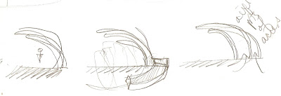
Here is a look at some of my first permutations of form. Taking on the program of a band shell / pavilion one is immediately drawn to the generic “shell” formation. These initial ideas explore how I may be able to contain the program while defining a unique structure and maintaining a clear biomimetic link. The biggest challenge for me at this point is looking for a way to combine the structure and its performance into a curvilinear form to provide for its function when it in fact wants to be a more rigid / rectilinear form (not to mention much easier!)
Looking at both the form and structure, I have simultaneously been exploring the potential mechanics of the project, more specifically, how each of the steel members can come together to achieve the desired structure and response. In terms of the mechanics of the structure, I feel the most difficult part in regards to my design is finding the balance between static and dynamic components and how these two approaches can in fact work seamlessly together.